Designing and Building a Macro Pad
Vim, Visual Studio, Visual Studio Code, Windows Powertools – I’m daily using a bunch of feature rich software. And everyone who once used Vim (or Emacs) knows there sometimes is no way around keyboard shortcuts! Or is there? Today I like to talk about the details of designing and building a macropad.
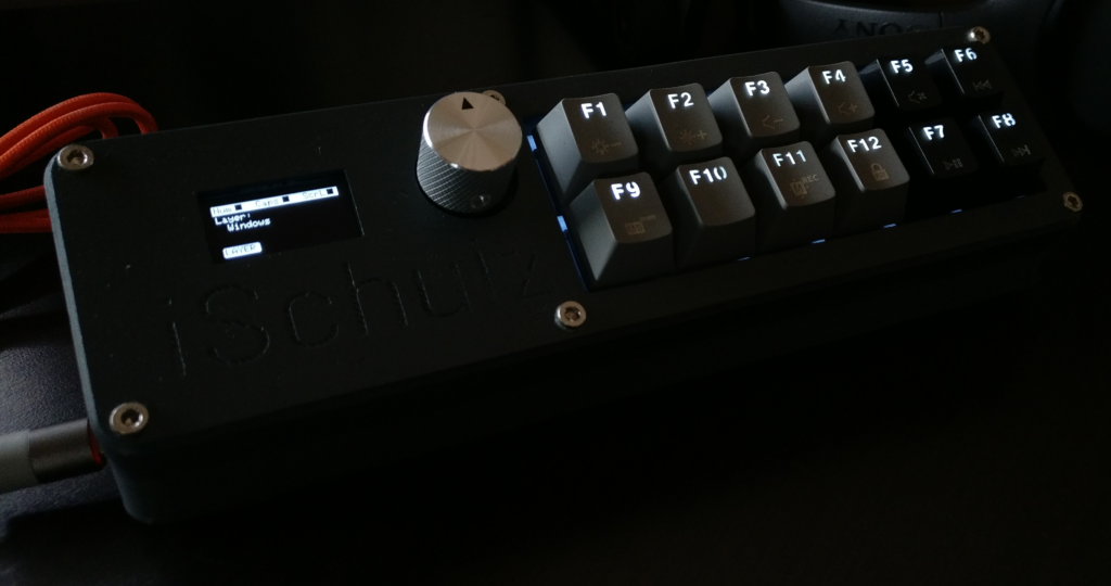
The final look
Keyboard Shortcuts
There’s a saying: ‘Can’t forget keyboard shortcuts if you never knew them in the first place.’ In general this is a rather dumb advice, because keyboard shortcuts can save an incredible amount of time when e.g. developing software. Sadly it’s partially true in my case… Visual Studio Code is a great editor, but for some reason the keyboard shortcuts I learned while using Visual Studio don’t apply in VS Code and I strongly refused to learn new keyboard shortcuts (above all if they are combinations like Ctrl+K, Ctrl+C, like two seperate shortcuts executed one after another, I mean come on). This does not mean I want to completely give up and forgo these features, quite the contrary. While looking for a solution I stumbled upon devices called stream decks, starting at 200€ per device, specifically aimed at online streamers. Stream decks are plastic cases with a couple of buttons on it and a USB cable to plug into your computer, ready to execute custom key combinations. Later I discovered that the term macro pad is used more often and covers a greater range of devices.
If the details are of no interest to you, then you may want to jump straight to the end of the page, download all the sources and just build the damn thing.
Macro Pads
Macro pads consist almost always of MX Cherry switches on top of a plastic case, protecting some electronics and wiring inside. One advantage over stream decks is they are much cheaper. Unfortunately there isn’t a wide range of products available, many of them are custom built and I didn’t find one that fits my taste. So why should anyone design and build a macro pad by him or herself? Because it’s easier than you think. And of course it will be a unique custom device, that perfectly fits your desk or workstation. On top of that I really learned a lot of new things about embedded devices, because I decided to incorporate an OLED display and rotary encoder on top of the twelve MX switches.
I must say at this point that having access to or even owning a 3D printer makes the process of building a case much easier and faster. I bought one while sitting in home office during the pandemic. If for any reason you can’t build one yourself, there is a decent barebone set from adafruit that is affordable and customizable.
Features and Parts
What features did I have in mind when thinking about a macro pad? First of all I needed twelve keys that I could map any shortcut or macro to. Secondly I wanted the abillity to dynamically change shortcuts and macros using presets. This would allow me to quickly change the functions of all keys when switching my editor or application. Finally I would need some visual feedback to display what preset currently is in use.
Parts needed for the macro pad would include twelve MX brown switches (tactile but silent), key caps, an rotary encoder with a knob and an OLED display. Each MX switche additionally needs a diode. When using translucent or backlit key caps one can just stick a 3mm LED onto the switch. I wired them up in series with a small resistor (this depends on LED color, I used white LEDs with forward voltage of about 3V). The heart of the device (or brain, feel free to comment on that) consists of a Arduino Pro Micro, well, not an original Arduino, but a similiar microcontroller with identical chipset (ATmega32U4). They are cheap, extremely small and the board has enough input pins to connect a keyboard matrix, I2C devices and interrupts. The biggest benefit you get from those boards is that they are equipped with full speed USB-transceivers. This means you are not restricted to communicate via serial port. Furthermore, it can emulate every USB device you’d like, e.g. a mouse or even a keyboard (hey, that’s what this is about!).
Design

First draft of parts placement
For a while now I’m used to SketchUp. In the past it was more architectual, now it’s 3D printing parts design. I know there are ‘real’ or more professional apps out there, but I still stick to SketchUp because it’s so intuitive (and maybe it’s because I’m too stupid). I don’t want to got too much into the details of how to use SketchUp and each step while I designed my macro pad, but demonstrate my workflow.
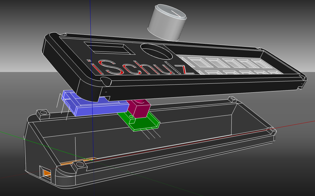
Exploded model showing inner electronical modules
In the beginning I took all the electronic parts and measured their dimension. I then created simple mockups of those parts and calculated the free space between them I would definitely need for wiring. After I had a nice initial sketch on paper I tried to transfer it into SketchUp. At first I created blocks, extruded them one after another and then refined the edges for a smooth surface. When using Sketchup be sure to create components or groups for individual parts, this makes it much easier to move them around without shifting any other surfaces or edges. Just for the record, it took me two prints for the base part and three prints for the top lid until all edges and holes were aligned due to margin of error. But this depends on the 3D printer and the filament material used (in my case plain PLA). For the assembly of the case I bought head threaded inserts for M3 screws which can be put into the base using a soldering iron. This is much better than just screwing into the plastic.
The electronic parts are using almost all available pins on the board. I didn’t create a circuit diagram when designing or building the pad, I only did a quick calculation (U = R*I) on what resistors I would need for the switch LEDs (they depend mostly on the color of the LED).

There are only two caveats to be aware of:
- The display (SSD1306) can only be hooked up to the I2C pins (the SCL and SDA pins)
- The pins of the rotary encoder (I used a KY-040, but you can also use one without a breakout board – just
make sure to wire it correctly) CLK, DT and SW need to be connected to one of the five interrupt pins. Otherwise debouncing and use in the firmware is going to be a struggle
And don’t forget to hook up diodes for the MX switches, otherwise you’ll probably kill them (although the board only delivers 3.3V).
Printing, Surface Finish, Wiring and Soldering
I print my parts always with 100% infill. I have patience and like sturdy devices (PLA isn’t the strongest material). Keep the margin of error in mind, print a few test parts with just a few layers and have a look if they can be aligned. This will save you much filament and time (printing time for the lid were 9 hours, the base took 23 hours). Let the finished prints cool down, use sandpaper going from coarse to fine and then give it some acrylic spray paintjob. This gives a nice surface finishing.
While soldering I didn’t try to cut up long wires for VCC or GND. Instead I just soldered through their coating until I hit metal. This way I saved heat shrinking tubes, which I needed elsewhere. On the wires that connect the LEDs I used hot glue, because there wasn’t much free space with the wires from the switches. Due to the lack of skills I can’t give any other advices (see image below…). For an overview of the full circuit see the image on the right. The wiring doesn’t have to exactly match the wiring in the image, but they have to match the ones defined in the firmware. Just make sure to connect the display to the SDA and SCL pins of the I2C bus. Also, not all pins support interrupt signals – there are only four available.
When putting it all together use low temperature on the heat threaded inserts, they sink really fast into the plastic. And don’t overtighten the M3 screws as it could loosen the inserts underneath. Carefully lay the microcontroller into place, use some glue on the bottom side and a little bit of hot glue on the usb port (they often break fast). Personal advice: wait with the screws until the firmware is flashed and working correctly – if you brick the board or get COM-port errors you can reset the board using a wire and short the RST and GND pins during code upload.

Soldering gore
Writing the Firmware
In this section I rather want to give an introduction into how a macro pad firmware can be designed, as the way I did it. You can take it and improve it as you like. I would be glad to read any comments you might have.
Which framework you use for writing and flashing the firmware is up to you. Five years ago I would have used something like Atmel Studio and a custom avr-dude configuration because at that time we mostly developed bare metal drivers and code. Meanwhile I got tired of the setup and simply use default libraries. For this project I just installed Arduino Studio, which comes with multiple AVR ISR programmers and went on to VS Code to install the Arduino extension. The board type should be Arduino Leonardo, this enables the USB transceiver. While many mechanical keyboards use similiar microcontrollers there are already prebuilt keyboard firmwares available, e.g. the QMK firmware (Quantum Mechanical Keyboards). But it seemed to be a bit overkill using such a firmware for a small macro pad with not more than twelve keys. Prebuilt firmwares tend to depend on particular pins or addresses one is bound to use, enabling only some of the features I was aiming for. This lead to writing my own firmware. In the end I got myself a macro pad with five different layers, three encoder modes and visual feedback (including nice logos while switching the layers). To save time and hassle I made extensive use of two libraries: the HID-Project and SSD1306-lib. The SSD1306-lib is a library for OLED displays by Adafruit. The HID-Project is a great library offering keyboard layouts for various languages, appropriate key codes and even multimedia functions. This helped a lot during programming of the keys.
Before we dive into the firmware I want to share a few words about microcontrollers and how they work. Usually you have two main routines: the setup and the loop. The setup will be called once in the beginning and usually does some initialization stuff, like setting pin numbers, defining addresses and activating resistors or interrupts. The loop will be called indefinitely until you turn the device off. Pretty self explaining. The only things that can randomly happen are ISR, but more on that later.
The Keypad
Let’s start with the keyboard matrix. The keyboard matrix or keypad is a table that maps pins to their corresponding switches. Depending on what key has been pressed, we get a signal at two pins: one that tells us which row the key was pressed and one that tells us the column. With this information we can deduct what key has been pressed. By the way, all keyboards sort of work by this principle. Typical macro keypads have a 3×4 layout, I chose a 2×6 layout resulting in the following keyboard matrix:
const byte ROWS = 2;
const byte COLS = 6;

char keys[ROWS][COLS] = {
  {'8', '7', 'B', 'A', '0', '9'},
  {'6', '5', '4', '3', '2', '1'}
};

byte rowPins[ROWS] = {A3, A2};
byte colPins[COLS] = {4, 5, 6, 19, 8, 9};

Keypad keypad = Keypad(makeKeymap(keys), rowPins, colPins, ROWS, COLS);
This may look out of order, but if you take a closer look at the final image you’ll see that I put the seventh and eighth key at the end. This is purely a e s t h e t i c because of my keycaps. Using the HID-Project library we simply can create a keypad with this layout and the provided pins.. If we then listen for a key, and eventually some key will be pressed, we can test against the chars from our keyboard matrix. This can be wrapped inside a switch statement:
char key = keypad.getKey();

switch (key) {
      case '1':
        Consumer.press(CONSUMER_BRIGHTNESS_DOWN);
        break;
      case '2':
        Consumer.press(CONSUMER_VOLUME_UP);
        break;
      case '3':
        ...
      case 'A': // Mute microphone
        Keyboard.press(KEY_LEFT_WINDOWS);
        Keyboard.press(KEY_LEFT_SHIFT);
        Keyboard.press(KEY_A);
        break;
      case 'B': // Lock computer
        Keyboard.press(KEY_LEFT_WINDOWS);
        Keyboard.press(KEY_L);
        break;
    }

delay(10);
Keyboard.releaseAll();
Consumer.releaseAll();
In this example I used some basic keyboard shortcuts as well as media or ‘consumer’ functions. Notice the releaseAll() calls at the end, without this call, the keys would keep on beeing pressed the entire time. This also comes in handy when programming Visual Studio macros, as they need you to press two keys two times one after another, e.g. Ctrl+K and then Ctrl+V. You would press two keys, add a small delay, release all keys and then press again two keys. And that’s it, there’s basically nothing left to do for the keys.
The Encoder
Our rotary encoder has two functions: the encoder function and a switch that can be pressed. For both we will be using interrupts. But before we can use interrupts we have to mark the pins as input pins, activate the internal pull-up resistor for the switch and define the ISR (Interrupt Service Routine) for each pin. You can also use the pull-down resistors if you like, this is a matter of taste as it just needs you to invert the logic (you would look for logical HIGH instead of logical LOW). Those resistors determine the state of your switches and prevent shorts in your circuit by either connecting to VCC or GND. If at our pin the input changes from HIGH to LOW our program will halt no matter at which position it currently is and jump straight to its ISR and execute it. This will be the case if we hit the encoder switch and by using the pull-up resistor the switch goes from VCC to GND, or from logical HIGH to LOW.
pinMode(0,INPUT);
pinMode(1,INPUT);
pinMode(7,INPUT_PULLUP);

aLastState = digitalRead(CLK_ROTARY);
attachInterrupt(2, updateRotaryState, CHANGE); // PIN 0, INTERRUPT_2
attachInterrupt(3, updateRotaryState, CHANGE); // PIN 1, INTERRUPT_3
attachInterrupt(digitalPinToInterrupt(7), updateSwitchState, CHANGE); // PIN 7, INTERRUPT_4

void updateSwitchState()
{
  switchState = digitalRead(SW_ROTARY);
  if (switchState == LOW) {
    if (millis() - lastMillis > DEBOUNCE_DELAY) {
      switch_mode = (switch_mode + 1) % NUM_MODES;
    }
    lastMillis = millis();
  }
}
The result of the ISR ‘updateSwitchState()’ will be extremely noisy, meaning the ISR will be fired multiple times after the switched was pressed. This is called bouncing and occurs typically in digital circuits. It can be tackled either by making changes to the circuit design and debouncing it using electrical components, or using software by waiting a couple of milliseconds until the state is not changing anymore. After debouncing the switch changes the encoder mode, which determines what value will be changed when using the rotary encoder. But how does a rotary encoder even work? Well, we have two input pins. When we rotate the encoder only one of the input states is changed. This incremental counter is also referred to as gray code, where two successive values or codes differ in only one symbol. We just need to store the old value of PIN_0 (CLK) so that we can compare it with the new value. If the two values differ we compare the current state with PIN_1 (DT) and
- if they are the same, the encoder was turned CCW
- if they are not the same, the encoder was turned CW
Now we can put all the logic into another switch statement:
void updateRotaryState()
{
  State = digitalRead(CLK_ROTARY);
  if (State != LastState)
  {
    bool cw = digitalRead(DT_ROTARY) != State;
     switch (switch_mode)
     {
      case 0:
        counter = cw ? counter+1 : counter-1;
        if (counter % 2 == 0) // debouncing, because encoder always counts 2
          current_layer = (counter / 2) % NUM_LAYERS;
        break;
      case 1:
        if (cw)
          Consumer.press(MEDIA_VOLUME_DOWN);
        else
          Consumer.press(MEDIA_VOLUME_UP);
        break;
      case 2:
        if (cw)
          Keyboard.press(KEY_UP_ARROW);
        else
          Keyboard.press(KEY_DOWN_ARROW);
        break;
     }
  }
  Keyboard.releaseAll();
  Consumer.releaseAll();
  LastState = State;
}
This lets you change the layer in mode 1, regulates sound volume in mode 2 and lets you scroll through documents in mode 3. I’m still looking for a better method of scrolling, but for now on webpages and documents this is sufficient.
The Display

The Splash Screen
The OLED display is connected via the I2C bus (Inter-Integrated-Circuit). This is a widely used communication bus for all sorts of microcontroller peripherals. I2C only uses two bidirectional channels: the Serial-Data-Line (SDA) and the Serial-Clock-Line (SCL). Modules that are connected to the I2C bus can be reached via their I2C address, which either is printed somewhere on its board or even can be defined using jumpers. Due to the design and the amount of work to setup the I2C communication on a microcontroller by hand (looking up the relevant registers and enabling them, writing communication protocols etc.) I recommend the use of existing libraries for any modules. They are widely used, mostly open source and highly reliable.
Using the Adafruit library the initialization of the SSD1306 is fast. It should look something like this:
#define SCREEN_WIDTH 128
#define SCREEN_HEIGHT 64
#define OLED_RESET     -1

Adafruit_SSD1306 display(SCREEN_WIDTH, SCREEN_HEIGHT, &Wire, OLED_RESET);
void setup()
{
  // SSD1306_SWITCHCAPVCC = generate display voltage from 3.3V internally
  if(!display.begin(SSD1306_SWITCHCAPVCC, 0x3C))
    for(;;); // allocation failed, don't proceed! loop forever
}
Rendering on the display is straight forward. The library provides functions to draw text in various colors, sizes and positions, simple geometric shapes as rectangles or triangles and even images. For the splash screen and the layer visualization I used Microsoft Paint and created 128×32 pixel logos. Be careful though, they take up a significant amount of space on the microcontroller. To convert the pixels into a byte array you can use one of the many apps found online. This is what the splash screen looks like in the firmware code:
static const uint8_t PROGMEM splash_logo[] = {
    0x00, 0x00, 0x00, 0x00, 0x00, 0x00, 0x00, 0x00, 0x00, 0x00, 0x00, 0x00, 0x00, 0x00, 0x00, 0x00,
    0x00, 0x00, 0x00, 0x00, 0x3f, 0xff, 0xff, 0xff, 0xff, 0xff, 0xff, 0xfe, 0x00, 0x00, 0x00, 0x00,
    0x00, 0x00, 0x00, 0x00, 0x40, 0x00, 0x00, 0x00, 0x00, 0x00, 0x00, 0x01, 0x00, 0x00, 0x00, 0x00,
    0x00, 0x00, 0x00, 0x00, 0x80, 0x00, 0x01, 0x43, 0xc7, 0x8f, 0x1e, 0x3c, 0x80, 0x00, 0x00, 0x00,
    0x00, 0x00, 0x00, 0x00, 0x81, 0xff, 0x83, 0x64, 0x28, 0x50, 0xa1, 0x42, 0x80, 0x00, 0x00, 0x00,
    0x00, 0x00, 0x00, 0x00, 0x81, 0xff, 0x87, 0x74, 0x28, 0x50, 0xa1, 0x42, 0x80, 0x00, 0x00, 0x00,
    0x00, 0x00, 0x00, 0x00, 0x81, 0xff, 0x87, 0x74, 0x28, 0x50, 0xa1, 0x42, 0x80, 0x00, 0x00, 0x00,
    0x00, 0x00, 0x00, 0x00, 0x81, 0xff, 0x87, 0xf4, 0x28, 0x50, 0xa1, 0x42, 0x80, 0x00, 0x00, 0x00,
    0x00, 0x00, 0x00, 0x00, 0x80, 0x00, 0x03, 0xe4, 0x28, 0x50, 0xa1, 0x42, 0x80, 0x00, 0x00, 0x00,
    0x00, 0x00, 0x00, 0x00, 0x80, 0x00, 0x01, 0xc3, 0xc7, 0x8f, 0x1e, 0x3c, 0x80, 0x00, 0x00, 0x00,
    0x00, 0x00, 0x00, 0x00, 0x80, 0x00, 0x00, 0x03, 0xc7, 0x8f, 0x1e, 0x3c, 0x80, 0x00, 0x00, 0x00,
    0x00, 0x00, 0x00, 0x00, 0x80, 0x00, 0x00, 0x04, 0x28, 0x50, 0xa1, 0x42, 0x80, 0x00, 0x00, 0x00,
    0x00, 0x00, 0x00, 0x00, 0x80, 0x00, 0x00, 0x04, 0x28, 0x50, 0xa1, 0x42, 0x80, 0x00, 0x00, 0x00,
    0x00, 0x00, 0x00, 0x00, 0x80, 0x00, 0x00, 0x04, 0x28, 0x50, 0xa1, 0x42, 0x80, 0x00, 0x00, 0x00,
    0x00, 0x00, 0x00, 0x00, 0x80, 0x00, 0x00, 0x04, 0x28, 0x50, 0xa1, 0x42, 0x80, 0x00, 0x00, 0x00,
    0x00, 0x00, 0x00, 0x00, 0x80, 0x00, 0x00, 0x04, 0x28, 0x50, 0xa1, 0x42, 0x80, 0x00, 0x00, 0x00,
    0x00, 0x00, 0x00, 0x00, 0x80, 0x00, 0x00, 0x03, 0xc7, 0x8f, 0x1e, 0x3c, 0x80, 0x00, 0x00, 0x00,
    0x00, 0x00, 0x00, 0x00, 0x80, 0x00, 0x00, 0x00, 0x00, 0x00, 0x00, 0x00, 0x80, 0x00, 0x00, 0x00,
    0x00, 0x00, 0x00, 0x00, 0x7f, 0xff, 0xff, 0xff, 0xff, 0xff, 0xff, 0xff, 0x00, 0x00, 0x00, 0x00,
    0x00, 0x00, 0x00, 0x00, 0x00, 0x00, 0x00, 0x00, 0x00, 0x00, 0x00, 0x00, 0x00, 0x00, 0x00, 0x00,
    0x00, 0x00, 0x00, 0x00, 0x00, 0x00, 0x00, 0x00, 0x00, 0x00, 0x00, 0x00, 0x00, 0x00, 0x00, 0x00,
    0x00, 0x1e, 0x00, 0x00, 0x60, 0x00, 0x00, 0x18, 0x00, 0xc0, 0x01, 0xf8, 0x00, 0x00, 0x00, 0xc0,
    0x00, 0x73, 0x80, 0x00, 0x60, 0x00, 0x00, 0x30, 0x00, 0x80, 0x01, 0xfe, 0x00, 0x00, 0x00, 0xc0,
    0x00, 0x40, 0xc0, 0xf0, 0x6f, 0x02, 0x02, 0x33, 0xf8, 0x00, 0x03, 0x06, 0x07, 0x90, 0x38, 0xc0,
    0x00, 0xc0, 0x07, 0xf8, 0x7f, 0xc6, 0x06, 0x33, 0xf9, 0x80, 0x03, 0x02, 0x3f, 0xf1, 0xff, 0xc0,
    0x00, 0x78, 0x0c, 0x0c, 0xe0, 0xc6, 0x06, 0x20, 0x31, 0x9f, 0xc3, 0x0e, 0x60, 0x33, 0x01, 0x80,
    0x00, 0x3e, 0x18, 0x00, 0xc0, 0xcc, 0x0c, 0x60, 0xc3, 0x1f, 0xe7, 0xfc, 0xc0, 0x63, 0x01, 0x80,
    0x00, 0x03, 0x98, 0x00, 0xc0, 0xcc, 0x0c, 0x61, 0x83, 0x00, 0x06, 0x00, 0xc0, 0x62, 0x01, 0x80,
    0x00, 0x81, 0x98, 0x19, 0xc0, 0xcc, 0x0c, 0x63, 0x03, 0x00, 0x06, 0x00, 0xc0, 0x66, 0x03, 0x00,
    0x01, 0xc3, 0x1c, 0x31, 0x80, 0xcc, 0x1c, 0xc4, 0x02, 0x00, 0x06, 0x00, 0xe0, 0xe3, 0x07, 0x00,
    0x00, 0xfe, 0x07, 0xe1, 0x81, 0x87, 0xf8, 0xcf, 0xf7, 0x00, 0x0c, 0x00, 0x7f, 0x63, 0xff, 0x00,
    0x00, 0x00, 0x00, 0x00, 0x00, 0x00, 0x00, 0x00, 0x00, 0x00, 0x00, 0x00, 0x00, 0x00, 0x00, 0x00
};
Demo
There is a bit of additional logic to shortly display a logo when changing the layer. This is done by waiting multiple times for a few milliseconds when the encoder has been turned, until approximately one second has passed. If the encoder is turned again before the second has passed, the delay is reset from within the ISR of the rotary encoder and the next logo will be displayed. This looks really nice in action.
Conclusion
I forgot to keep track of the time I invested into this project, but I would say it took aproximately two weekends. After a short time I already got really used to work with it. And in the evening it just looks nice thanks to the display and the LEDs. In the end I just had a lot of fun while designing, building and reworking the macro pad.
Okay, I don’t have custom key caps, telling me the function of each key, so in the end I have to remember the layout. But this is more convenient than having to press two or three buttons at once, sometimes multiple times. This leads me to improvements I want to tackle over the next weeks, like for instance displaying the key functions of the current layer. Hey, this is what display were invented for… Another nice feature would be integrating MIDI features – yes, even this is possible using the ATmega32. But for this device, it won’t be more as some basic channel functions, mute buttons or a simple drum pad. Another thing I noticed is, that I don’t see the time (or even date) when using certian apps in fullscreen mode. So displaying at leas the current time (and having the option to turn it off) would be a neat feature. I would simply integrate an RTC (Real Time Clock) module and a tiny battery for storing the set time, after all two pins are still free on the board. The last improvement would of course be a real PCB, that would add to the stabillity of the build and definitely save more space inside the case – possibly to the extent that the case can be shrinked down.
Anyway, thank you very much for reading this post. Have fun building your own macro pad and even more when using it!
Source
If want to build your own macro pad you find all the files (design and firmware) in my Google Drive:
https://drive.google.com/drive/folders/10k9_uAzoXWHZnKhLd42YDzCb2wnVogiy?usp=sharing
Links
HID-Project: https://github.com/NicoHood/HID
SSD1306-lib: https://github.com/adafruit/Adafruit_SSD1306